Choosing High Temperature Ceramic Bushings starts with understanding the conditions they must withstand. A bushing near a furnace door faces different demands from one inside a pump or kiln. Temperature is only part of the picture. Load, speed, vibration, atmosphere, and exposure to chemicals also shape performance.
Small details matter. A ceramic grade that works well in dry heat may behave differently in steam or corrosive gases. Alumina, zirconia, and silicon carbide each offer distinct properties, but no material is best for every application. Consider the operating temperature range, not just the highest temperature listed on a product page. Frequent heating and cooling can create thermal stress, while poor alignment may concentrate loads and cause premature damage.
Fit and installation deserve equal attention. Measure the shaft and housing carefully, and confirm tolerances with the supplier. Ceramics are hard and wear-resistant, yet they can be brittle. A tight press fit or a sharp impact during assembly may create cracks that are difficult to see. That risk is easy to underestimate.
Reliable selection depends on application data, not guesswork. Review technical datasheets, ask how test conditions compare with your equipment, and request guidance for unusual environments. If possible, trial the bushing under representative conditions before scaling up. One point may remain uncertain: real service life can differ from laboratory results. Careful evaluation helps narrow that gap and supports a more dependable choice.
Before selecting a high-temperature ceramic bushing, define the real temperature range at the contact surface. A furnace setting of 800°C may not match the bushing’s temperature during operation. Record steady temperatures, startup peaks, and how long each peak lasts. Also note temperature changes during cooling. Rapid shifts can create thermal stress. Small details matter.
Load requirements need equal care. Identify radial and axial forces, shaft speed, vibration, and expected operating hours. A bushing carrying a light, steady load faces different demands from one exposed to repeated impacts. Ceramic materials can perform well in heat, but they may be brittle under shock or uneven loading. Check the material’s rated limits and test data for your actual conditions. Estimates are useful, but they can be wrong; measure where possible.
Tips: Share temperature logs and load measurements with the supplier. Ask whether ratings assume dry running, a specific fit, or a particular speed. A tight housing fit can restrict thermal expansion. Leave that unchecked, and even a suitable material may fail early.
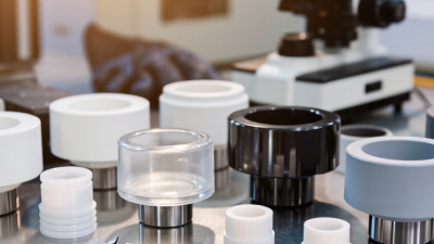
For a high-temperature ceramic bushing, compare more than advertised maximum temperature. Alumina is widely used because it is hard, electrically insulating, and relatively affordable. Its thermal conductivity is modest, so heat may remain concentrated near a rubbing surface. Rapid heating or cooling can also stress it. A small bushing beside a hot shaft may behave differently from a large, slowly heated component. Size matters.
Silicon carbide conducts heat well and usually handles thermal shock better than alumina, making it useful when temperatures change quickly. Silicon nitride combines high strength with low thermal expansion, which can help where alignment must remain stable. Stabilized zirconia offers toughness and low thermal conductivity, but its higher expansion can complicate tight clearances. No material wins every comparison. A property chart cannot fully represent friction, shaft finish, atmosphere, or uneven heating. Check the actual grade, operating load, and temperature cycle, then test the fit if possible. That step is easy to overlook.
A high-temperature ceramic bushing should be sized for its working condition, not just its room-temperature drawing. Record the shaft diameter, housing bore, bushing length, and expected temperature range. Also note whether the shaft rotates continuously or moves intermittently. These details affect heat buildup, wear, and the clearance needed for reliable operation.
Ceramic and metal parts expand at different rates. Calculate the running clearance using the actual materials and operating temperatures; a cold fit that looks generous can become tight after heating. Avoid assuming that a tighter fit always improves alignment. Excessive interference can stress a brittle bushing, while too much clearance may cause vibration or uneven wear. Small details matter. Check the manufacturer’s technical data, and have critical fits reviewed against the full assembly.
State dimensional tolerances clearly, including bore and outside diameter, roundness, and any required concentricity. Surface finish matters too: a rough shaft can wear a polished ceramic bore faster than expected. Build tolerance stack-up into the design, especially when the housing, shaft, and bushing come from separate processes. It is tempting to specify very narrow tolerances everywhere, but that can raise cost without improving performance. I would still revisit the first fit after testing; real heat cycles can expose assumptions that a drawing cannot.
This illustrative calculation estimates the minimum cold diametral clearance for an alumina bushing running with a 316 stainless-steel shaft from 20°C to 500°C. It assumes average thermal expansion coefficients of 8 × 10⁻⁶/°C for alumina and 16 × 10⁻⁶/°C for stainless steel, plus a 20 μm running allowance. Actual requirements depend on material grades, temperature distribution, load, lubrication, and mounting conditions.
Using the chart: Treat the values as a starting point, not a universal fit specification. Select the bushing bore and shaft dimensions, then account for their manufacturing tolerances so the minimum assembled clearance remains adequate at operating temperature. Confirm the design with the ceramic supplier or a thermal-fit calculation for the actual application.
A high-temperature ceramic bushing must suit the actual chemical environment, not just the rated temperature. Identify liquids, vapors, cleaning agents, and process residues that may contact it. A mildly acidic condensate can affect one ceramic differently from another. Check the material’s compatibility data at operating temperature, and ask whether brief exposure during shutdown also matters. Small details matter.
Wear depends on what moves against the bushing and what gets trapped between surfaces. Dust, hard particles, and misalignment can turn a smooth shaft into an abrasive contact point. Note shaft material, load, speed, and start-stop frequency. If possible, inspect worn parts from a similar assembly; their scratches and uneven contact patterns can reveal more than a general wear estimate. Not always obvious.
Friction also changes with surface finish, lubrication, temperature, and contact pressure. A dry-running design may need different clearance from a lubricated one, especially as parts expand during heating. It is easy to focus only on maximum temperature; that can be a mistake. Ask for test conditions that resemble the real duty cycle, including heat-up and cool-down. When data is limited, record assumptions and review them after early service inspections. One choice rarely fits every installation.
How to Choose High Temperature Ceramic Bushings
Verify Installation Compatibility and Service Requirements
Start with the installed assembly, not the bushing’s advertised temperature limit. Check shaft diameter, housing bore, operating speed, radial load, misalignment, and the surrounding atmosphere. A ceramic part may tolerate heat yet crack under a tight press fit or sudden temperature change. Small details matter. The ASM Handbook, Volume 2, lists typical thermal expansion coefficients near 8 × 10⁻⁶/K for alumina and 17 × 10⁻⁶/K for austenitic stainless steel. Across a 50 mm diameter and a 500°C rise, that difference suggests roughly 0.23 mm of unequal free expansion. Treat this as a screening estimate, not a final tolerance.
Confirm hot clearances, mounting support, and lubrication needs with the actual grade data. NIST’s Structural Ceramics Database (SRD 30) compiles mechanical-property data for structural ceramics; use values for the specific material and test conditions. Ask for strength, thermal-expansion, and temperature-dependent property information, then compare it with the shaft and housing specifications. Check the hot fit. Also inspect the assembly method: ceramic bushings generally need even support, clean contact surfaces, and protection from edge impact. I would still be cautious about any calculation based on room-temperature values; real fits depend on temperature gradients, surface finish, and restraint. A tidy drawing can miss those.
| Selection area | Material or dimension | Typical reference / verification | Installation and service implications |
|---|---|---|---|
| Material screening | Alumina (Al₂O₃) | Typical thermal expansion: about 7–8 × 10⁻⁶/K. High-purity grades may be considered for oxidizing service at temperatures around 1,400–1,600°C, subject to grade and load limits. | Check purity, thermal gradients, impact risk, and chemical compatibility. Do not assume the maximum material temperature is a suitable continuous bushing operating temperature. |
| Material screening | Silicon carbide (SiC) | Typical thermal expansion: about 4–5 × 10⁻⁶/K. Some grades are used in oxidizing service at temperatures around 1,400–1,600°C; atmosphere and grade affect the usable limit. | Often considered where wear, thermal conductivity, or thermal shock resistance matters. Verify oxidation, corrosion, porosity, and bonding or impregnation details for the selected grade. |
| Material screening | Silicon nitride (Si₃N₄) | Typical thermal expansion: about 3–3.5 × 10⁻⁶/K. Many grades are screened for oxidizing service up to roughly 800–1,000°C, depending on grade and exposure. | Useful where strength and thermal-shock resistance are important. Confirm the grade’s chemical resistance and allowable temperature under the actual mechanical load. |
| Material screening | Zirconia (ZrO₂) | Typical thermal expansion: about 10–11 × 10⁻⁶/K. Many stabilized grades are screened for service around 800–1,000°C, with limits depending on stabilization and environment. | Its expansion differs from alumina and silicon carbide; check shaft and housing expansion together. Verify stabilization type and aging or phase-stability limits for the service conditions. |
| Running fit | Bore, shaft diameter, and operating clearance | Specify the cold bore and shaft dimensions, tolerances, roundness, and surface finish. Determine the required clearance at operating temperature rather than selecting a universal room-temperature clearance. | Account for differential thermal expansion of the shaft, bushing, and housing. Check the full temperature range for both seizure risk and excessive play. |
| Housing fit | Outside diameter, seat, and retention method | Confirm housing bore tolerance, concentricity, support length, and whether the design uses a clearance fit, compliant layer, or specified interference fit. | Ceramics have limited tolerance for tensile stress and edge loading. Avoid an unverified press fit; use only the fit and assembly method approved for the bushing geometry and ceramic grade. |
| Load and motion | Radial load, speed, oscillation, and start-stop duty | Provide load, shaft speed or sliding velocity, duty cycle, misalignment, and expected shock loading. Check the selected grade’s allowable stress and wear data for the complete assembly. | Do not assess suitability by temperature alone. High contact stress, misalignment, vibration, or impact can cause premature cracking or wear. |
| Lubrication and environment | Dry running, lubricant, gas, and process chemicals | Identify lubricant type and temperature limits, or confirm dry-running conditions. List exposure to steam, acids, alkalis, molten materials, dust, and process gases. | Ceramic chemical resistance is material- and grade-specific. Verify both the ceramic and any coating, seal, adhesive, or secondary component against the process environment. |
| Thermal cycling | Heating rate, cooling rate, and temperature gradient | Record minimum and maximum temperatures, ramp rates, dwell time, and any localized heating or cooling. | Rapid or uneven temperature changes can generate thermal stress. Check the material’s thermal-shock capability and the assembly’s expansion compatibility. |
| Assembly and inspection | Insertion, alignment, and edge condition | Use clean, aligned mating parts; inspect the bore, ends, and contact surfaces for chips, cracks, or handling damage before installation. | Prevent impact, point loading, and forced insertion. Follow the specified assembly procedure and recheck shaft freedom and alignment after installation. |